
Datalogger
Abstract
The datalogger is used to monitor the onboard CANbus and collect data about the battery, maximum power point trackers and motor driver. The datalogger has the possibility to read his own sensors as well, with an onboard IMU and I2C expansion header as well as four UART serial ports. The datalogger can support three different CAN busses, two of the busses are wired through the SPI peripheral since there is kernel support for the CAN controller, the third bus uses the SAMA5D36's CAN peripheral. The datalogging system can write to two SD cards, the second SD card is used as a fail-safe in case the first one fails or corrupts. The datalogger can push data over the internet with the use of a mini PCIe compatible modem and a valid SIM card, some modems can receive a GPS signal as well which can be used to geographically stamp the data.
Requirements
- Supply voltage 12 volts, supports up to 32 volts
- Has at least two separate CAN buses available
- Write to redundant SD cards
- Communicate over the internet for remote data evaluation
- Receive a GPS signal
- Ethernet functionality
- Wifi through a USB dongle
- Has a backup power supply for safe shutdown
- Possibility to connect an LCD display
- On board IMU
The datalogger will be built around the Acme systems Acqua, this system on module uses a SAMA5D36 as its main CPU and has all the peripherals we desire and is well documented. More information about the SOM can be found on the manufacturers website (https://www.acmesystems.it/acqua). The Acqua board has been chosen because the SAMA5D36 that is used on the board supports CAN, MMC, UART, Ethernet, SPI, I2C, USB and has support for an LCD.
Component selection
The schematics are available below under "Schematics"
MPU
Selected: Acmesystems ACQUA-512E-N256-D36
The choise for the Acqua was made based on it's power consumption, the number of peripherals and the fact that the system-on-module is very well documented.
Modem
There is a mPCIe slot on the board which can fit a modem, we use the slot in combination with the quectel EC-20. This modem can communicate over 3G and 4G networks and receive a GNSS/GPS signal get the boats position.
Super Capacitors
The super capacitors where chosen because of their leakage current, capacitance and voltage rating. The specifications for the surge current en ESR are less intresting since the ammount of current drawn is not that excessive and only for a minute when the main power source is not available. The super capacitors are used when the LTC4412 meassures the main power failure, when this happens an P-channel MOSFET is switched so the capacitors will be the power source. When the P-channel MOSFET is conducing the LTC4412 signals the MPU which upon receiving the signal starts shutting down.
Voltage Regulators
Since the systems input voltage was specified at a minumum of 12V and a maximum of 32 V and most components operate at 3.3V or 5V there must be a voltage conversion for this we use converters with a buck topology since the input is always higher than the output. While doing research into switching regulator IC's we found that Linear makes quite efficient regulators whit efficiencies up to 95%. The LT8610 buck converter is one of the IC's with a 95% effiency and can deliver 2.5A output current which is plenty for the 3.3V and 5V rail (which has USB ports). The charging of the supercaps is a one time only event and we chose the LTC3630 for this, this regulator is a bit cheaper and charges the caps using pulsed current outputs.
SD slot
Selected DM3AT-SF-PEJM5
We wanted a push-push SD card slot for easy insertion and removal. This SD slot has just that and the footprint is quite compact which is a plus for component placement.
RTC
Apart from the internal RTC in the acqua we wanted an external RTC as redundancy. The choise was made for the RV-1805-C3 which is a very efficient RTC in a small but easilly solderable package. The IC communicates using the I2C protocol which is fast enough for reading the time upon boot.
IMU
The IMU (Intertial meassurement unit) collects data about angle the boat is in. Based on the raspberry pi datalogging systems which had an IMU as well we knew how much G force we can expect on the boat, this parameter as well as effiecency and operating voltage made us choose the ICM-20602.
LCD
The LCD is used as feedback from the system to the driver, it show the data received over the CAN bus that is usefull when sailing such as the battery percentage and cell voltage as well as how much power is comming in from the solar deck. Acmesystems has a couple of LCD's available and we quite liked the 5.0 inch display. Implementing the display started as something we just liked to do for fun, but after we had an issue with a wave of salt water in Monaco and our former display we are going to implement it as our main display.
SD ESD protection
Selected: CM1624
The ESD protection device CM1624 is made specifically for SD cards and has the pullup resistors integrated, in it's uDFN package it doesn't take up much space on the board. The main disadvantage of the IC while designing the board was the stock at our suppliers which is why we placed external pullup resistors as well so the CM1693 can be placed as well.
CAN Transceiver
Selected: MCP2561
The MCP2561 was selected since we used the same IC on our first raspberry pi based datalogging system.
Schematics
The full set of schematics for the datalogger are made available upon request free of charge, by requesting the CAD files you agree to not use the design files for commercial purposes.
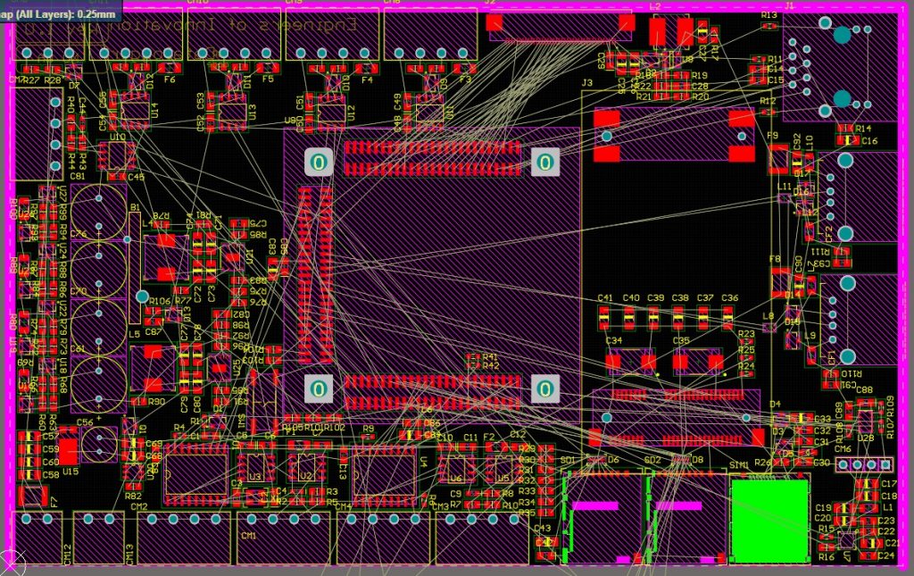
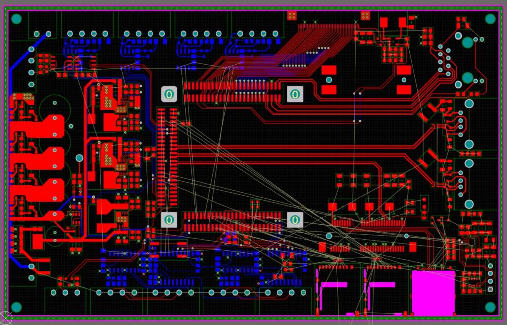
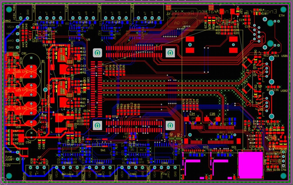
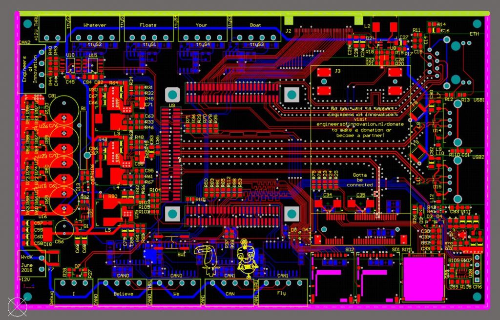
Layout
The process of routing the circuit board from component placement to the finished board. When the component placement is done the routing starts with the traces with the highest frequency signal and we work our way down to the signals that are DC. when the routing process is completed we start working on the silkscreen adding our sponsors and giving it a personal touch by adding some (arguably terrible) jokes made during the late night meetings while still in the design process.
Software architecture
Will become available soon!
Thanks to

