
Motordriver
Abstract
Our new boat will be powered with a BLDC (brushless direct current) motor motor instead of a brushed motor, which will make the drivetrain more efficient. This will require a new, more complicated, controller. Efficiency is the most important factor in this design, not only because of the limited power of the solar panels, but an efficient motor controller also produces less heat which ensures easier cooling techniques.
Requirements
Because the motor (driver) is primarily used during the Solar Sport One (SSO) races, they should comply with their regulations (Link)
To reduce the development time spent on the embedded software, the motor driver was made compatible with the VESC BLDC driver software project. This software can do sensorless field-oriented control (FOC) with minimal development effort. All specifications of the motor driver are summarized below:
- VESC compatible hardware
- As efficient as possible; >99.5% at around 1kW of motor power
- Up to 5kW with minimal cooling
- Max power up to 15kW
- Modular design for easier future updates
- Fully isolated data interfaces
- Upgrade path for more advanced motor control (FPGA)
- Input power between 32.5 and 58 V DC, 48 V DC nom.
- High ambient temperature est. 70° C
- Interface communication
- CANbus
- UART, for debugging purposes
Power stage
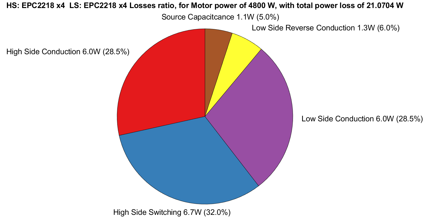
The most important part of the design for efficiency are the MOSFETs driving the motor, and is therefore the starting point of the design. MOSFETs were chosen on a figure of merit (FOM) based on their on-resistance RDS(on) over their Gate charge QG. This list of devices is dominated by GaN-based transistors, the top contenders of which were included in more sophisticated losses estimation.
GaN FETs have slightly different power loss parameters than conventional silicon MOSFETs as there is no body diode present in the semiconductor structure, which means there are no reverse recovery losses, something that is a significant loss especially for large and fast switching devices. The rest of the power losses are quite similar and were calculated for the FETs with the highest FOM. An example of the power loss for four parallel EPC2218s, in a three-phase bridge configuration, is shown in the pie chart below.
 While this efficiency is quite good, a problem with cooling these small power MOSFETs at higher powers is foreseen. To reduce the losses and spread the heat out over a larger surface area, a configurable power-stage was implemented which can switch between 4 and 8 parallel devices. Efficiency calculations of both implementations are plotted below.
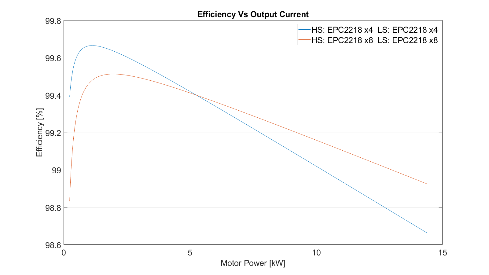
And while the difference in efficiency seems quite small between the two implementations, the real benefit comes when the power dissipation per MOSFET, and thus the ease of cooling, is plotted.
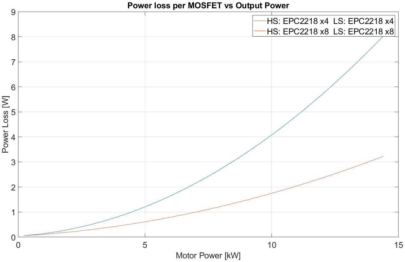
At high powers about one third of the cooling per FET is required by switching to the 16-FET per bridge configuration.
Power Circuit Layout
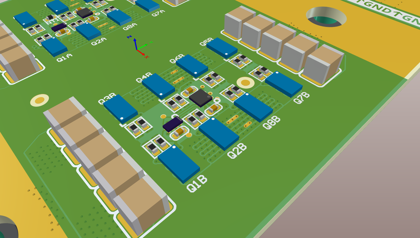
GaN FETs also have the potential for very high switching speeds and low dead-time , which in turn increases the efficiency. These factors however are highly dependent on parasitic inductance and thus the layout of the power-stage is of utmost importance. The image below shows two parallel low-side and two parallel high-side MOSFETS with their ceramic decoupling capacitors.
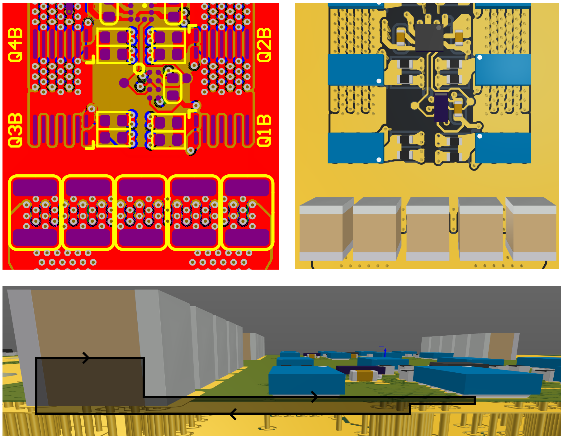
The low inductance layout used is based around reducing magnetic field loop area (in gray) as much as possible, this is achieved by interleaving opposite current paths and making sure current return paths flow on adjacent layers.
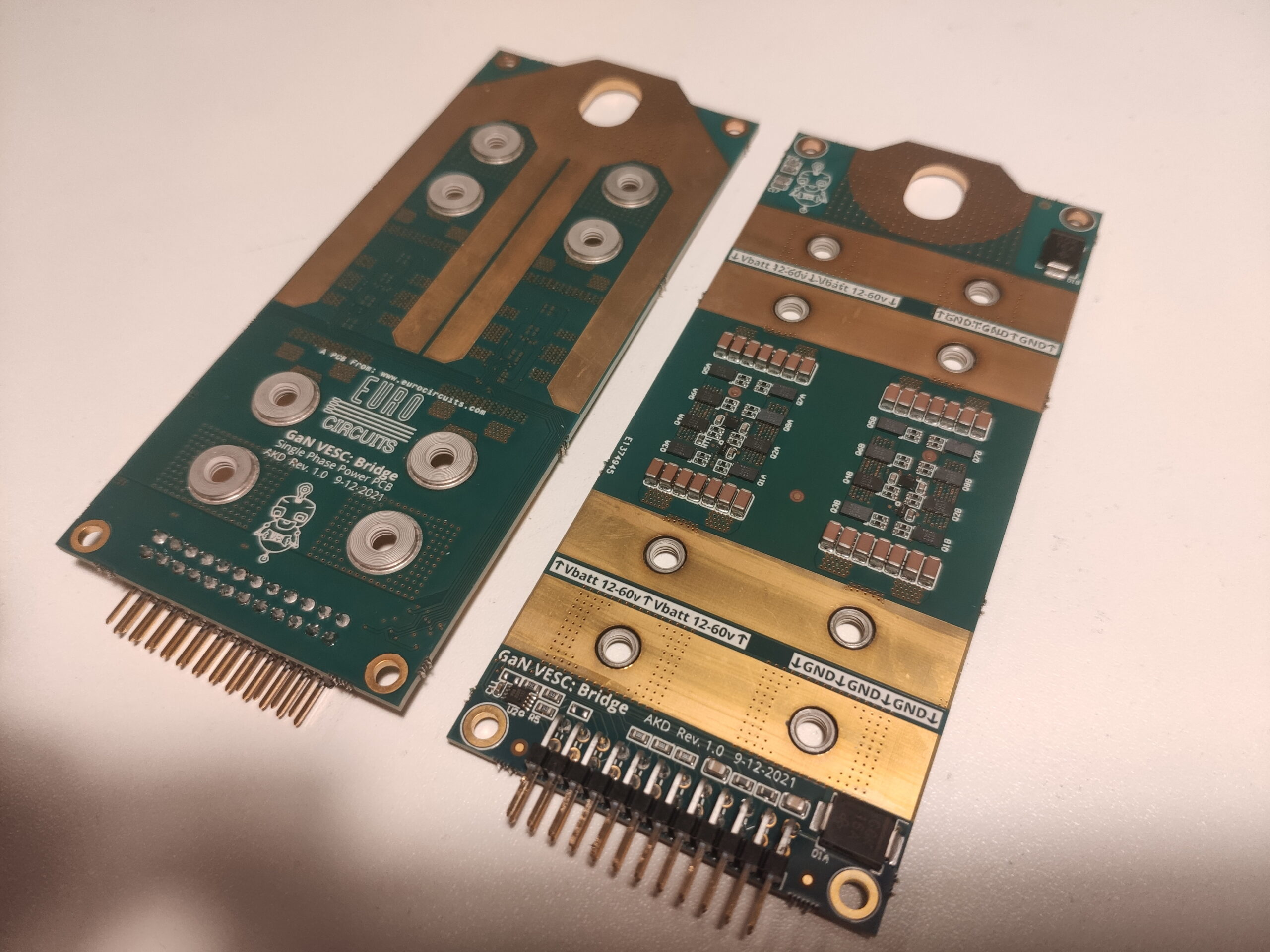
Eurocircuits is the perfect assembler for these boards, as their impressive 0.125 mm clearance on 60 um (2 OZ) thick copper is impossible to get at other poolable PCB services. This with small 0.4mm vias make sure that both the DC resistance and the parasitic inductance can be as low as possible.
The rest of the layout consists of a double mirror-symmetric set of 8 MOSFETS with the low-side FETs near the driver, which is positioned in the middle, the switching layout with all four layers can be seen below.
The final layout shown below consists of one phase per PCB with large copper planes to accept 10mm copper busbar, the far end has a connection point for a single motor wire. The near end has a right-angle connector to connect back up to the controller PCB.
Controller
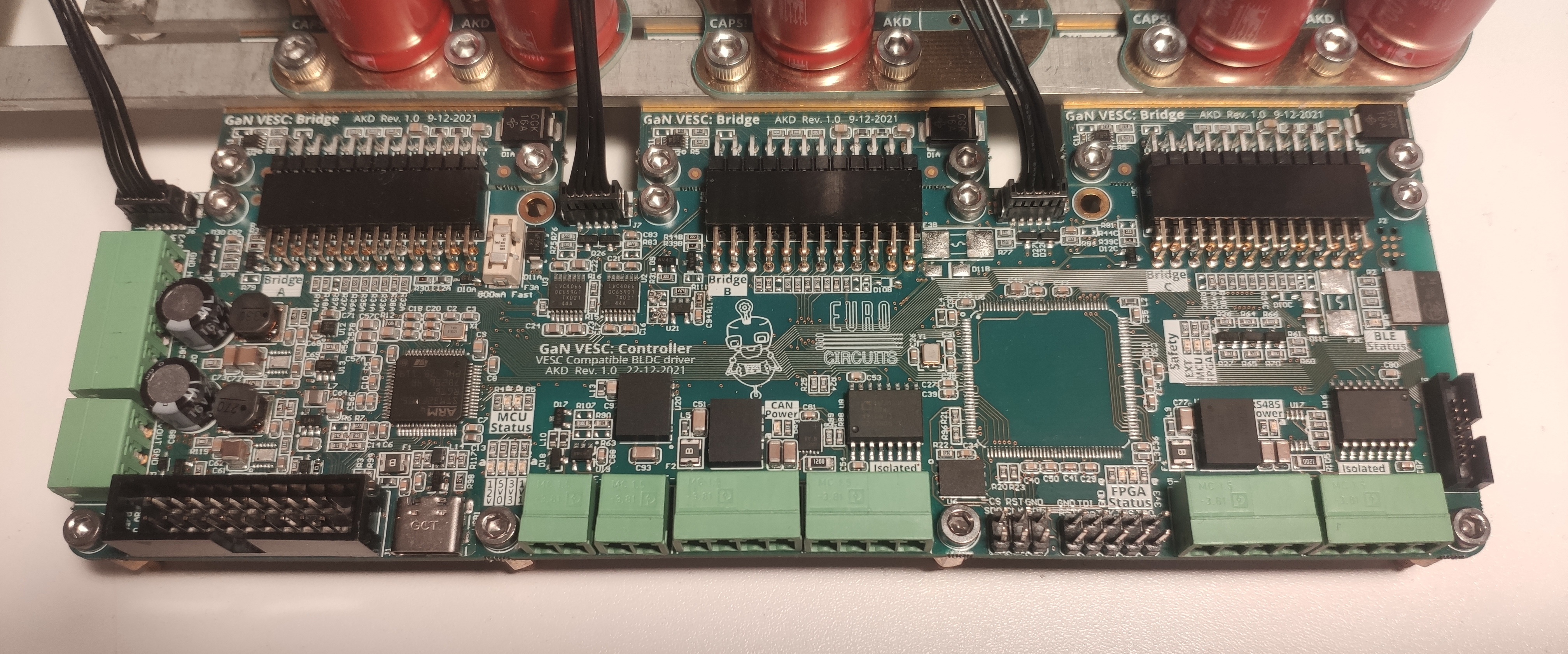
The heart of the logic is situated on the controller board shown below. It is based around an STM32, which is used to run the embedded software from the VESC project. The supported communication protocols are CAN and RS485. The three GaN phases are connected as shown at the top of the image. An FPGA is present to process the incoming delta-sigma current signals for controlling the phases.
Electrolytic Capacitor mount
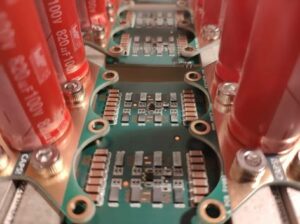
To have the decoupling capacitors as close to the switching action as possible, they are mounted on top of the copper busbars running past all the phases as shown below. Their PCB layout is symmetrical on top and bottom so that the board can be flipped to accommodate both sides of the Phase-PCB. The mounting holes on these PCBs are there to potentially accommodate heat sinks for better heat dissipation.
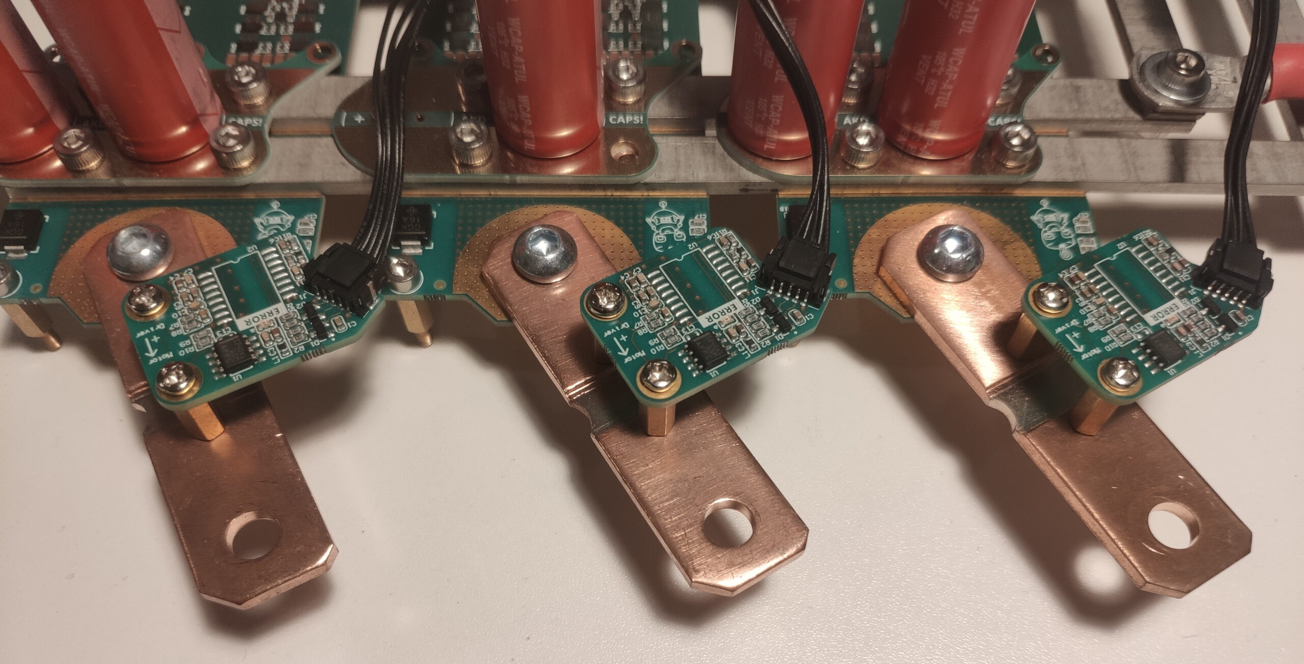
Current Sensors
The Current sensors use an external large sense resistor, as temperature swings would decrease the accuracy of PCB mount shunt resistors. The current sensor boards consist of a simple analogue current shunt amplifier feeding back analogue signals directly to the MCU. These amplifiers, however, have a hard time dealing with the large common mode jumps seen at the output of the motor driver. A future proof solution to this is an isolated delta sigma ADC which digitizes the shunt voltage directly, this requires some signal processing on the FPGA which will be added in future software implementation.
Schematics
The full set of schematics for the motor driver are made available upon request free of charge, by requesting the CAD files you agree to not use the design files for commercial purposes. Please see a live view of the Altium project below.
Layout
The full set of layout for the motor driver are made available upon request free of charge, by requesting the CAD files you agree to not use the design files for commercial purposes. Please see a live view of the Altium project below.
Software architecture
The software is available upon request free of charge, by requesting the software files you agree to not use it for commercial purposes and comply with all licences.
Thanks to